SAVELINE ® system
Comprehensive measurement of hot spots
The SAVELINE® system can comprehensively monitor refractory linings for local overheating (hot spots), during operation. This is achieved with the help of encapsulated linear sensors, which are not sensitive to electrically conductive deposits (metal condensates, moisture, carbonaceous refractory materials) Special sensor ceramics enable measurement in the temperature range between 150°C (302°F) and 1350°C (2462°F).
 |
 |
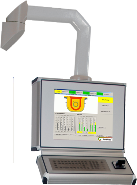
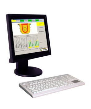
| Hardware components of the SAVELINE ® system Left: Control and visualisation unit (C&V) Right: Measuring unit |
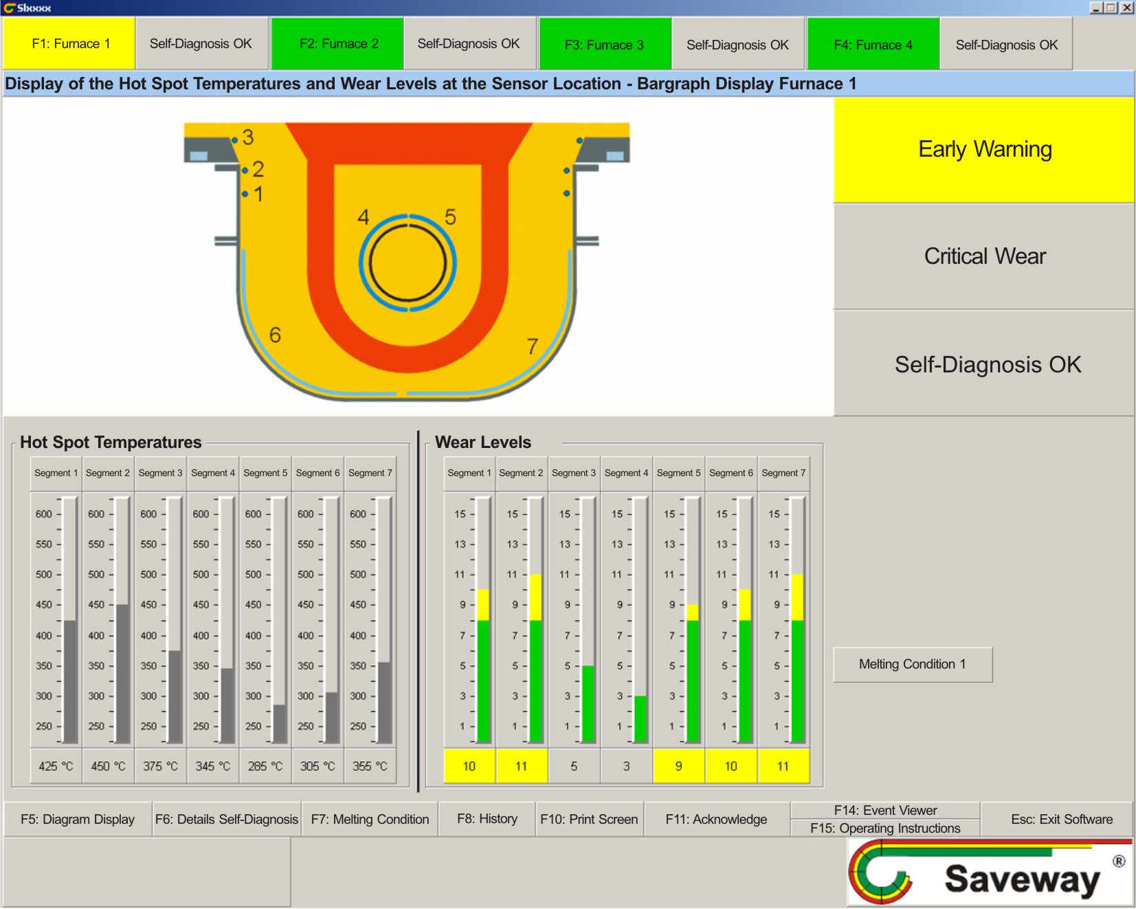
Operator display of the SAVELINE ® System using the example of a channel furnace |
Application
Application
The extraordinary flexibility of the technology enables the adaption to many customized tasks.
| SAVELINE® installation on a channel furnace inductor (animation) |
Application examples:
+ Coreless induction furnace
+ Coreless inductor
+ Channel furnace
+ Cupola
+ RH-Degasser
+ AOD-Converter
+ Ladle
+ Arc furnace
+ Submerged arc furnace
+ Blast furnace
+ Imperial smelter
Benefits
Benefits
Significantly improves safety
for operating staff and plant, because furnace damage and molten breakouts can be safely avoided
Optimize operating costs
by reducing the costs of maintenance and production losses
Increase equipment up-time
based on the risk-free increase of Service life and predictability of relining
Product attributes
Product attributes
- Simple and safe handling
- Robust equipment for working in harsh environments
- Multifunctional application on various furnaces
- Easy integration in existing networks
- Automatic self-diagnosis of all SAVELINE® devices
- Electrically autonomous measuring system
- Fast remote service via TeamViewer
- Continuous data storage
- Easy integration into furnace controls
- Combinable with SAVEWAY® and SAVEDRY®
SAVELINE ® sensor:
- Operating range: 150 °C (302 °F) to 1350 °C (2462 °F)
- Outside diameter: 3 bis 6 mm (0.12 to 0.24 inch)
- Lenght: variable
- Insensitive to moisture and conductive deposits
- Flexible
Functionality
Functionality
SAVELINE® measures not simply at one point, but always the highest temperature over the entire sensor length, compared to other methods of temperature measurement. The measurement is based on the strong temperature dependence of the resistivity of certain ceramic materials which are contained in the SAVELINE® sensors. It is displayed in form of a bar graph or chart, separately for each segment. Critical conditions are immediately displayed on the operators‘ display screen.
At relining, the sensors can be arranged in prefabricated segments or directly on the inside of the steel or shell wall. To comprehensively monitor distinct areas, the sensors can be arranged in a serpentine fashion easily due to their flexibility. The partition of critical areas into separate segments allows localized hot spot detection.
Features
Features
- Additional external dual display
- Furnace shell identification
- Gradient analysis
- Peak level indicator
- Interactive readout of the operator displays
- External LED status display
Additional external dual display
This separate parallel display always shows the same screen as on the control and visualization unit, without time delay. Longer distances can be reached, with a maximum distance of 100 m (328 ft) to the control and visualization unit.
There are two different variants:
 |
 |
| External opti panel | External TFT display |
Furnace shell identification
With the help of this feature, the system automatically identifies which furnace shells are currently connected to the system. The identified furnace shell will be monitored in the wear and history display.
Gradient analysis
With the aid of the gradient analysis, a critical increase of penetration for each segment will be displayed separately. That means metal is penetrating the lining at an unsafe rate. A critical increase of wear levels can be set differently for each segment.

Gradient analysis using the example of a cannel furnace
Peak level indicator
The peak level indicator refers to the temporary display and storage of the maximum wear level per segment until manually reset. Quick and easy view of the maximum wear is possible. This quick overview is an enormous benefit, for example at, shift changes.
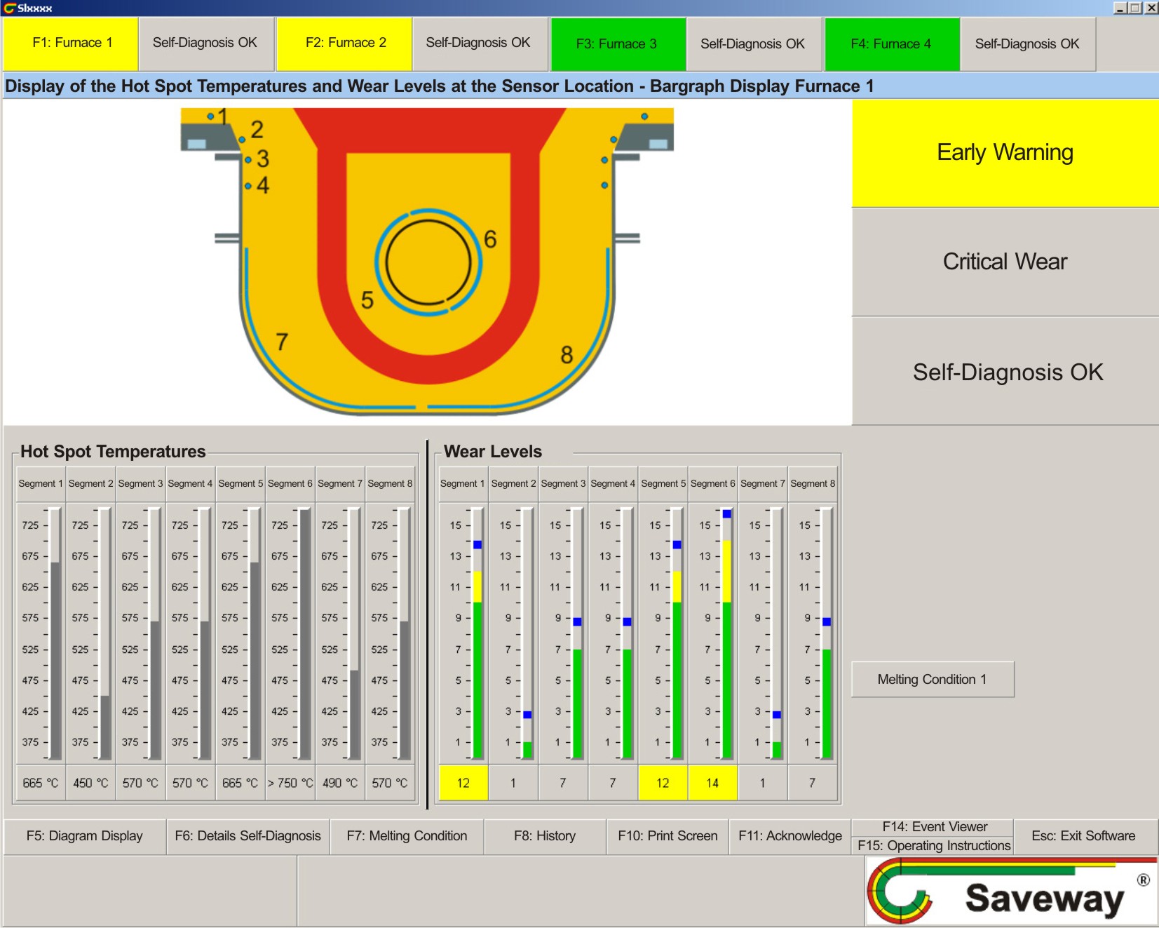
Peak level indicator using the example of a channel furnace
Interactive readout of the operator displays
This feature allows the automatic switching between operator displays of all furnaces connected to the system. Activation and deactivation is done manually. This display is advantageous; especially at greater distances between furnace and the control and visualization unit.
External LED status display
The three-step status stack (ANDON lights), which is designed for floor and wall installation, shows the current wear condition of the furnace as Green, Yellow or Red.
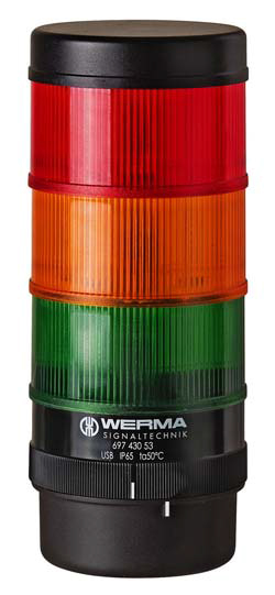
External LED status display